- SWISCA
- 白皮书
白皮书
Roller Mill Drive – Whitepaper ROMIL
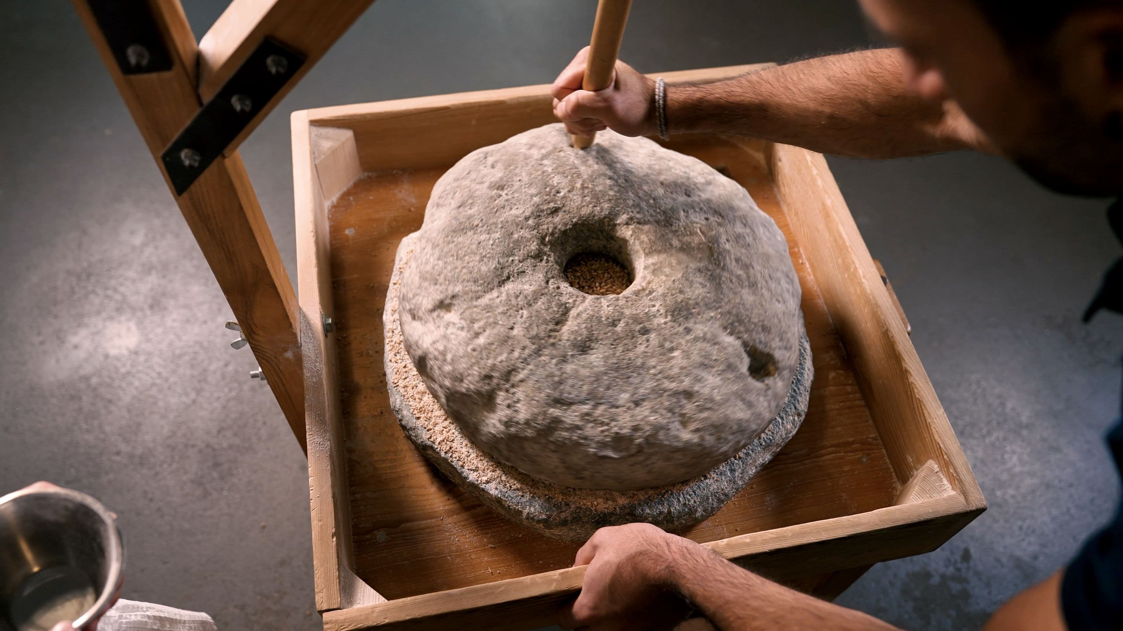
The crushing of cereal grains has historically been accomplished through pressure and shearing. Approximately 27,000 years ago, grinding stones were first employed for this purpose. Utilizing an oscillating motion of the grinding stone against a stationary surface, the grain trapped in between could be effectively processed.
In many subsequent developments, the principle of maintaining one grinding surface stationary while the other moves relative to it was preserved. This is achieved, for example, through a horizontal or vertical pair of disks, a cone with a counterpart, or a roll with an adjacent counter surface. In all these variations, the stationary mating surface doesn‘t actively engage in the grinding process; it primarily absorbs forces without undergoing movement. This paradigm shifted with the advent of roller grinding in the 18th century.
The movement of the previously stationary counter surface was recognized to offer several advantages. By configuring it as two parallel, counter-rotating rolls operating at distinct speeds, pressure and shear could be precisely controlled as influential variables, independently and purposefully. This setup enabled enhancements such as increased throughput and desired selective grinding. Thanks to many other parameters, multi-stage, sophisticated grinding processes were developed.
From the perspective of machine manufacturers, one aspect of roller grinding stands out: the „overdrive,“ which refers to the coupling of the two roll speeds. The technically straightforward design, consisting of two differently sized intermeshing spur gears at one end of the roll pair, represents an ingenious solution. In the configuration typical for grain roller mills, the slow roll must always be braked to maintain the desired speed ratio. However, if the grinding speed ratio remains constant, the considerable braking force applied to the slow roll can be efficiently transferred back to the fast roll via spur gears.
In a typical roll pair, the fast roll is powered by an electric motor, which in turn drives the slow roll through the material in the grinding gap. The overdrive mechanism prevents the slow roll from reaching the speed of the fast roll and redirects the braking power back to the fast roll. Consequently, a significant amount of mechanical power is effectively circulated.
Measurements indicate that the braking power on the slow roll is notably high in comparison to the power introduced into the roll assembly. On smooth passages, this braking power typically exceeds the grinding power by a considerable margin. Therefore, it is paramount that this excess power is efficiently transferred back to the fast roll.
The rolls become tense due to the ground material and the overdrive. A torque ratio can be calculated from the measured torque on the rolls, which typically falls within a certain range under typical operating conditions for roller mills. The influences on this torque ratio are complex. The braking power is determined by the speed ratio and the above torque ratio:
– The lower the speed of the slow roll compared to the fast roll, the lower the required braking power.
– The greater the tension between the rolls, the greater the required braking power.
Of course, the above does not address the effective grinding power, which is the power converted as the difference between the drive and braking power in the grinding gap.
Pressure can be easily varied during operation by means of a variable grinding gap. Conversely, varying shear, generated by altering the speed ratio during operation, comes at a high cost. This can be achieved by feeding back the braking power with associated losses and/or through a technically complex machine design. As a result, the flexibility gained through a variable speed ratio has often been overlooked, optimized only for specific processes and kept constant for the majority of operations..
The comparison of the two passages indicates that the performance of the reduction passage surpasses that of the break passage, despite its lower grinding capacity. Of course, this also applies analogously to less heavily utilized passages.
Nowadays, the simplest method to incorporate a variable speed ratio during operation is to equip each roll with its own motor and link the corresponding frequency converters in the intermediate circuit This individual roll drive can be configured as a direct drive or as a remote motor with belt drive. In such a system, the braking power from the generator-driven motor of the slow roll is dissipated from the system and reintroduced via the motor on the fast roll. Consequently, the motor on the fast roll must be chosen considerably larger than in a roll package with a fixed speed ratio.
In order to fully utilize the degree of freedom in a roll assembly with a single roll drive, the rated torques or rated power of the components must be sufficiently high. This aspect should not be underestimated. Conversely, there is no need to worry about the generally unknown power flow with fixed overdrive. If the power transmission from the fast roll to the product to the slow roll is high, then the overdrive power is high, resulting in more power being circulated. This does not impact the required drive power and the typical assumptions for power requirements (kW per t/h) used in calculations.
However, this is not the case with the single roller drive. The intricate power transmission in the grinding gap directly affects the required drive and braking power and the selection of component sizes, as the power must be entirely extracted and reintroduced electrically into the assembly. Incorrect drive and braking power can result in reduced throughput, the need to decrease grinding work, or the inability to maintain the optimal speed ratio for the process.
In a grain mill, there are numerous break and reduction passages where a variable speed ratio during operation may not be beneficial. However, variability can be advantageous for specific passages to enable the production of specialized products. For instance, this could include a grist passage where, in extreme cases, the fluting position (back/back to cutting edge/cutting edge) is changed, or a smooth passage where a notably high shear is desired with a high-speed ratio.
Energy efficiency can be achieved through the optimization of the mill diagram and the use of energy-efficient machinery. The recovery of energy, which must first be added to a system, leads to poorer energy efficiency. The power losses are greater with individual roller drive, as energy recovery for this application is not energy efficient.
If the variability of the speed ratio is required for the production of special products, this can be easily implemented for selected passages with individually assigned motors. The technical simplicity and high efficiency of the traditional belt drive transmission are advantageous for an energy-efficient roller mill. In combination with modern product level control and feeding, as well as precise adjustment and stability of the grinding gap through robust roll packages, an overall energy-efficient milling process can be achieved. For technical systems, only the required energy in a suitable form should generally be supplied for optimal energy efficiency.
The trend towards process optimization with sustainable machines in the milling industry not only saves costs and supports millers in their work. Innovativesolutions optimize energy-efficient and food safe processes and thus the work of the operating personnel.
制粉行业的工艺优化。
数字化,也就是产生和处理数字型数据,是制粉行业的一种趋势。如果在一个测量位置实时测量时测量水分、流量、重量和密度(容重)并进行数字化处理时,出现的错误和偏差会更少,甚至可以排除错误。在面粉厂运行过程中,数字化能够提高效率,从而提高经济效益。多功能测量系统产生的数据为数字型,适用于在线优化质量和工艺
在制粉行业中,精确的重量测量已经得到了重视。由生产工艺和质量要求来决测量参数和测量精度,才能用于工艺监测和质量保证。除了计量流量和重量外,多功能称重系统还可以实时测量和数字化处理水分、温度和密度。实时数字测量的成本和误差小于实验室人工采样、分析和评估以及耗时的手工过程。云方案和远程维护允许数据存取,用于内部过程控制和产品可追溯性。采用了基于以太网的现场总线模块ProfiNet和Ethernet/IP或Profibus以及RS 485接口。
制粉行业中的秤、流量控制器和微量添加秤的核心是控制系统。最先进的称重系统配备了耐用、用户友好和可靠的触摸屏。用于云解决方案和远程维护的网络服务器模块能够实现最佳的数据访问和使用,用于粉率计算、产品追溯和库存。秤可以自主操作,也可以连接到工厂控制系统和ERP系统。基于以太网的ProfiNet和EtherNet/IP现场总线模块或Profibus和RS485接口就是为了这个目的。在断电的情况下,秤受控的关闭,所有数据都保存在秤控制系统中。在许多工厂,安装有20到30年历史的控制器的衡器。备件往往不再可用,接口也已过时。秤的控制可以很容易地用现代化的控制系统替换,生产数据可以得到最佳利用。
在制粉行业中,通过测量水分、流量、重量、温度以及密度,采用多功能称重系统进行工艺优化的趋势不仅节省了成本,而且大大提升粉师的工作效率。合理的数字化可改善工艺管控和操作人员的工作。
秤的控制改造
制粉行业的每一家公司的数字化战略和转型的组织都会不同。成功实施数字化战略的先决条件是详细规划路线图和需要的活动。任何没有操作性的数字战略都是无效的。在工厂的运营过程中,数字化能够提高效率,从而改善其盈利能力。信息越来越多地被数字化存储并可用于电子数据处理。
通过精确的重量测量进行的内部过程控制变得越来越重要。由生产工艺和质量要求来决测量参数和测量精度,才能用于工艺监测和质量保证。与物联网兼容的称重系统以数字形式生成的数据也适用于在线优化质量和工艺。控制改造可实现连接性,因此延长了机器使用期。过时的控制缺乏与现场总线的连接,也没有能力连接到互联网以利用远程维护和云解决方案。为了数字化,数据必须能够被访问和随时可用。云解决方案和远程维护能够为内部过程控制和产品可追溯性实现最佳的数据访问和使用。现代化的秤控制配备了网络服务器模块和触摸屏,耐用而可靠。
制粉行业数字化战略的实操需要可连接物联网、云解决方案和远程维护。称重系统的控制改造可以延长机器的使用期,经济划算,并使数字数据可访问,用于电子数据处理。
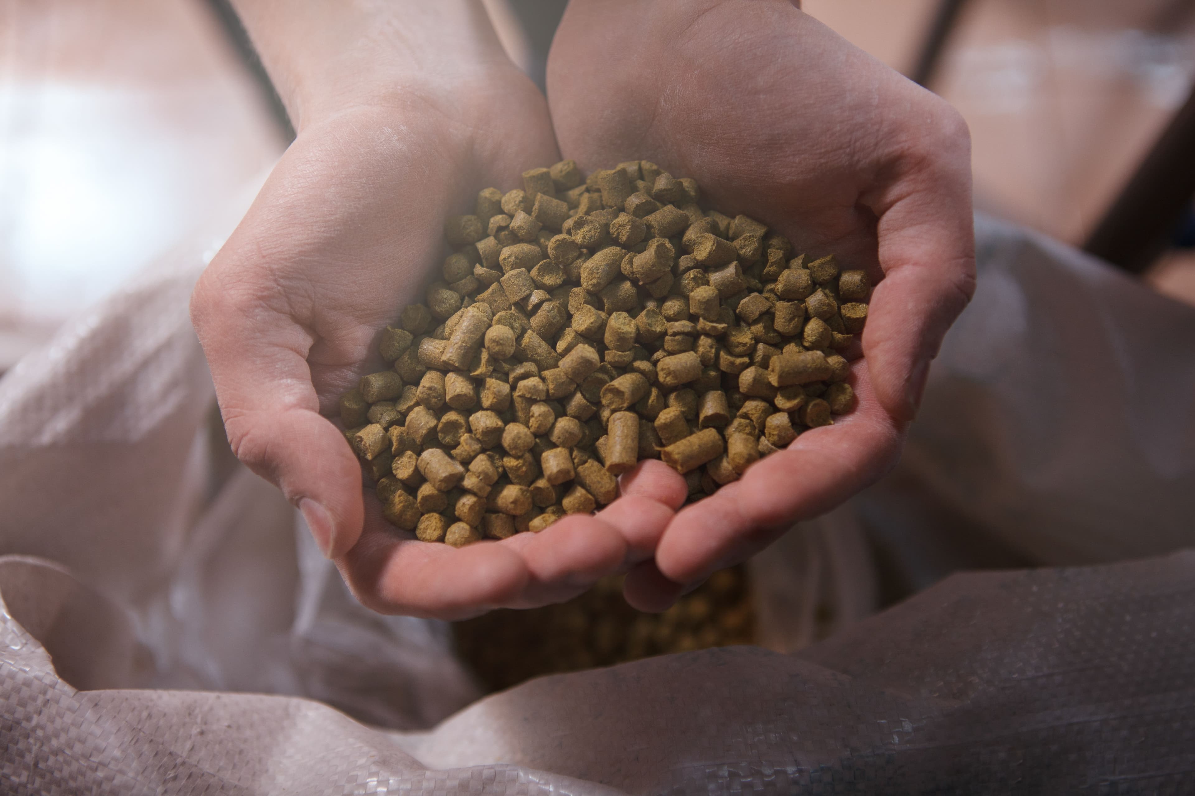
来自SWISCA的啤酒花添加
水、麦芽和啤酒花是啤酒的基本成分。水是基础,麦芽提供强度,啤酒花提供香味。啤酒花是这三种原材料中最昂贵的。为什么啤酒中的啤酒花如此重要?这些成分带来了辛辣的苦味、酸味甚至是果味,并具有镇静、防腐和稳定泡沫的作用。啤酒花是一种攀援植物,属于麻科的一个植物属。雌性植物带有宝贵的伞形花序,其中含有树脂和精油,为啤酒增添风味和花香。
在瑞士的阿彭策尔(Appenzell)的乡村,直接位于阿尔卑斯山脚下,洛赫家族酿造了一种非常特别的啤酒。根据精确的配方,使用啤酒花和麦芽,以及来自传说中的阿尔卑斯山湖水,直接来自源头。这使得Appenzeller啤酒特别和独一无二的风味。家族酿酒厂的第五代人正在创造新型啤酒。这个工匠的创新精神是多品种和高品质的来源。Appenzeller啤酒出口到德国、英国、俄罗斯、加拿大、台湾、日本、美国和新加坡等地。创业公司SWISCA AG于2018年在阿彭策尔(Appenzell)成立,由食品加工和称重技术的开发、设计和销售方面的经验丰富的专家组成。注重质量和创新对SWISCA AG来说至关重要。由最好的技术和经验丰富的工程师,SWISCA AG实现了创新产品的开发,用于世界市场的食品加工厂。
为了生产特殊的啤酒,Appenzeller啤酒厂Locher和SWISCA AG共同开发了一个创新的称重系统,用于准确地定量喂料酒花颗粒。工艺技术的一致性保证了创新啤酒品种的高质量。优秀的酿造艺术和新的称重技术的结合是由瑞士联邦的新区域政策促成的,该政策促进了加强瑞士农村地区的创新、增值和竞争力的项目。区域发展基金提供的财政援助由瑞士政府和州政府平均分担。该项目使阿彭策尔(Appenzell)州内的价值链得到了延伸。形象和产品加强了区位商业。该项目有助于促进尖端技术、数字化和确保有吸引力的工作。
改善的谷物调制保持高出粉率
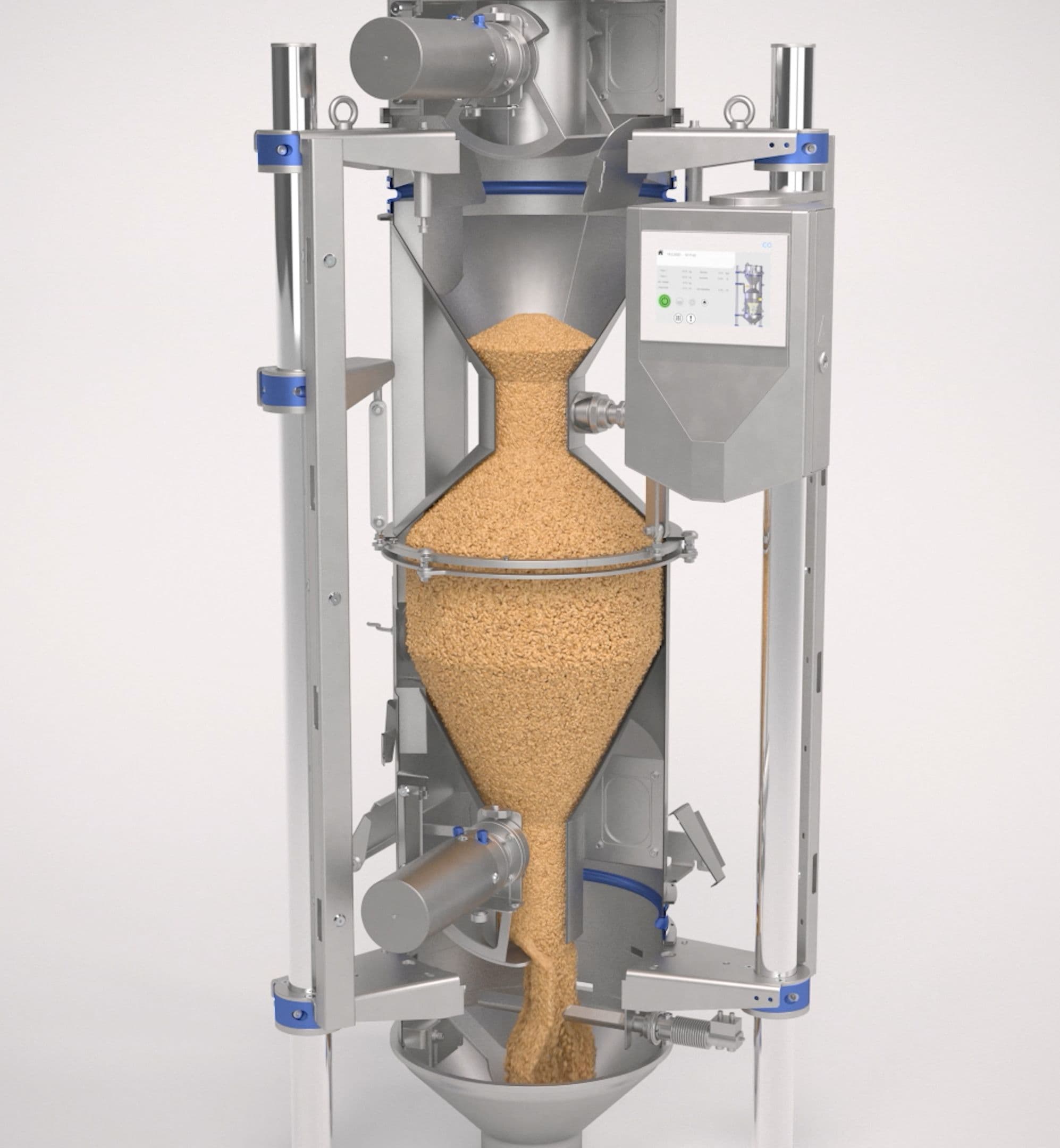
面粉厂的一个重要工艺是润麦,以确保均匀研磨和高出率。润麦有两个重要的好处,一是使小麦处于最佳研磨条件,二是加水以获得商业收益。小麦通过加水和润麦,麸皮层变得坚韧而有弹性,胚乳也软化。这是在研磨过程中最有效地分离它们的最佳条件。为了使润麦效果最好,重要的是加水尽可能均匀地分布在谷粒的表面,在润麦仓中使其能够均匀地渗透到胚乳中。润麦通常一个能源消耗大的生产过程,同时在卫生方面也非常关键,因为关乎到食品。除了技术的和经济的,微生物影响方面也越来越重要。达到或超过食品安全标准要求的挑战性越来越高。
除了在线测量物料的流量,差分计量秤还用于对谷物的其他参数进行精确的测量,如水分、密度和温度。制粉工艺要求谷物的准确数据,物料的温度、密度和水分含量是必须的。物料流量和水分的测量与物料密度相关。创新的控制系统易于对电容式水分传感器校准,并与实验室确定的值进行准确比较。差分计量秤的创新结构和配置,在测量流量和总重量比传统设备更精确。使用最先进的控制技术和称量算法,用出料门后测量,即使秤再充料时也如此。这个附加的冲击测量消除了秤再充料时的不确定性,改进估计法的测量精度。由于这个附加测量,系统全部以重力方式工作,并且可以连续监测和重新调整出料门的开口。高精度和连续的优点在一个差分计量秤上得到了最佳结合。秤的精度提高提供了一致的润麦条件,这样加水也可以非常准确。
自动液体流量控制器和带有水分测定系统的差分计量秤配合使用,可以精确地加水。差分式计量秤同时测量物料的流量流速和水分。控制系统计算出所需的水量,并非常精确地控制液体流量计和出料门。通过多功能称重系统对流量、水分、温度的连续测量和控制以及对所需加水量的计算,实现了高效的过程控制。带有电动阀门定位器和蓄电装置的高质量控制阀能够实现高的工作范围。计量水量的准确性受流量计的质量和精度的影响很大。正确设计的水过滤器对于分离任何可能的杂质至关重要。自动液体流量控制器也适用于氯化水(55℃,600ppm)或蒸汽,采用卫生设计制造,由不锈钢组成。不需要任何额外的电气控制单元来测量水流量或谷物中的水分含量。
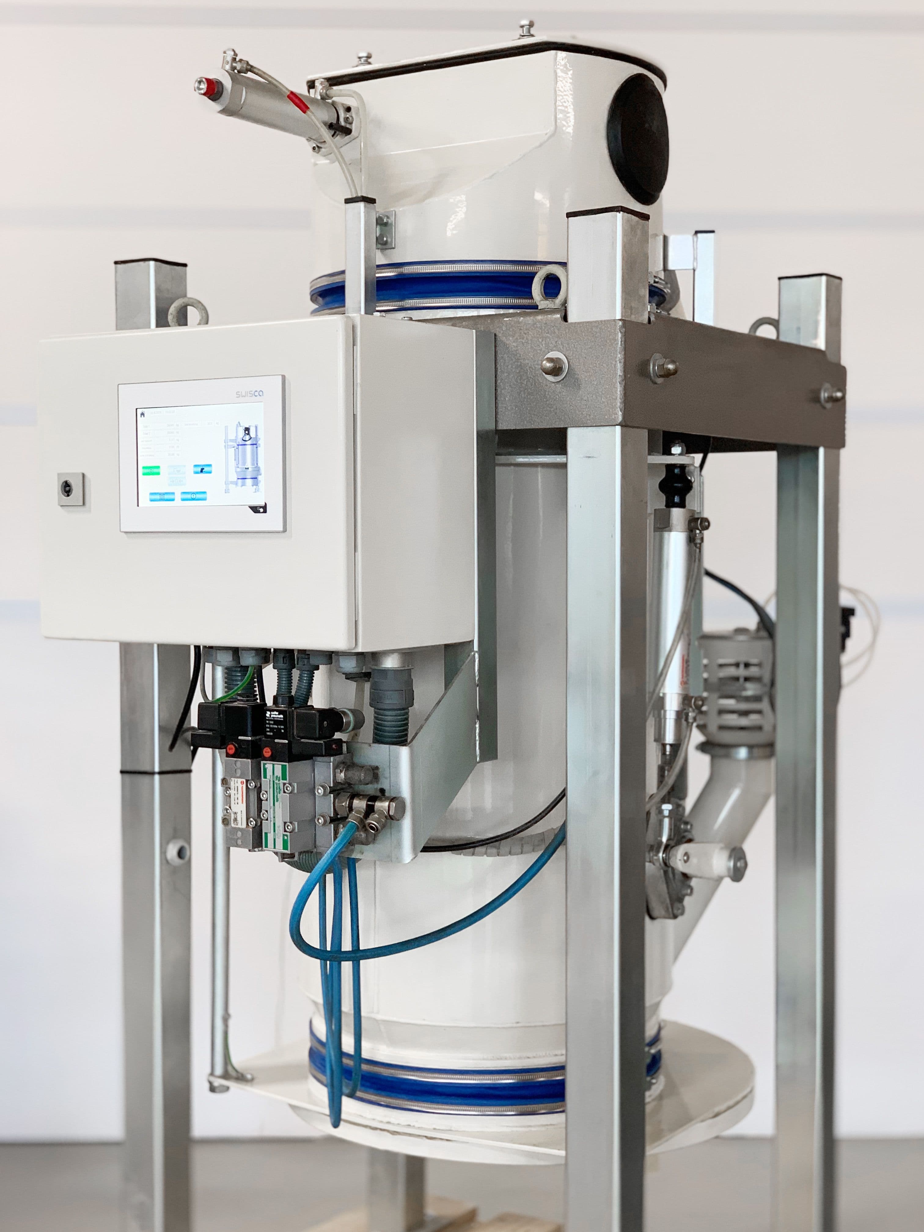
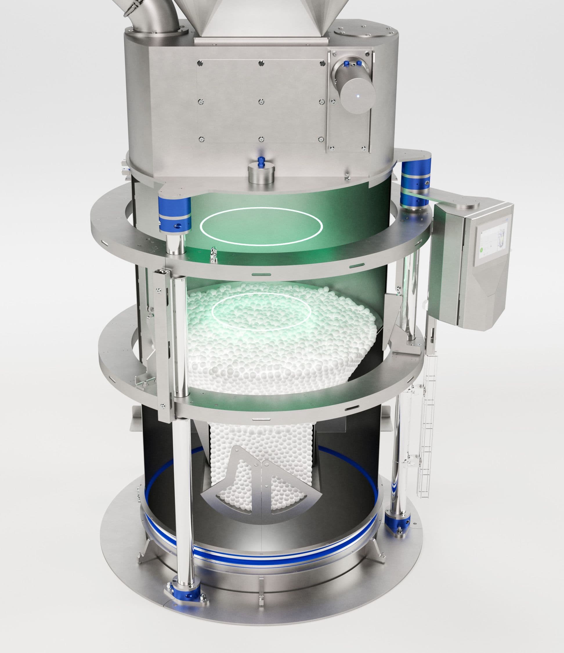
着水润麦是面粉厂的常用工艺。水的添加率可高达7%,同时要求小麦磨损和破损最小。在面粉厂,小麦着水是一个关键控制点。大多数着水设备需要定期进行清理。一旦机器停机,会出现病菌和细菌的生长。这种消极影响肉眼可见,通常也会有明显的气味。细菌生长确认可以用实验室测试数据作为参考。传统着水设备内部,必须手动清除污垢和谷物残料,以避免或控制污染。如果着水设备在较长时间内不运行,存在着微生物污染新加工小麦的潜在危险,而且难以去除。当这些被污染的小麦进入磨粉时,用它生产的面粉也会有含有增加的微生物数量。创新的着水机将污染的风险降到最低,并可实现自动在线清洗(CIP)。有些情况下,要求水的添加量非常小,同时要均匀分布在颗粒表面。这将是一个真正的挑战。在这种情况下,下面所示的机器是一个正确方案。通过板条将小麦流形成一个帘状。添加的水通过两边径向排列的喷嘴雾化成细小的水滴。这些水滴与下落的谷物碰撞,并附着在表面。在生产过程许可的时候,会执行自动清理周期。可扩展的冲洗喷嘴由清洁机构驱动,以实现整个内部的最佳清洁。清洗过程中的废水以及收集的残余物的处理,通常可自动化。
在制粉工业中,利用智能系统进行工艺优化是趋势,可以节约成本,还支持粉师,促进运营卓越。带有精确的流量、密度和水分测量的节能解决方案、卫生的加水技术、资源效率高的着水工艺和在线清理清技术,有助于将小麦调制系统提高到一个新的水平。这种新一代的水分管理系统是可持续的,需要更少的设备和各类控制,大大减少了能源,是满足和超越最严格食品安全标准的重要一步。
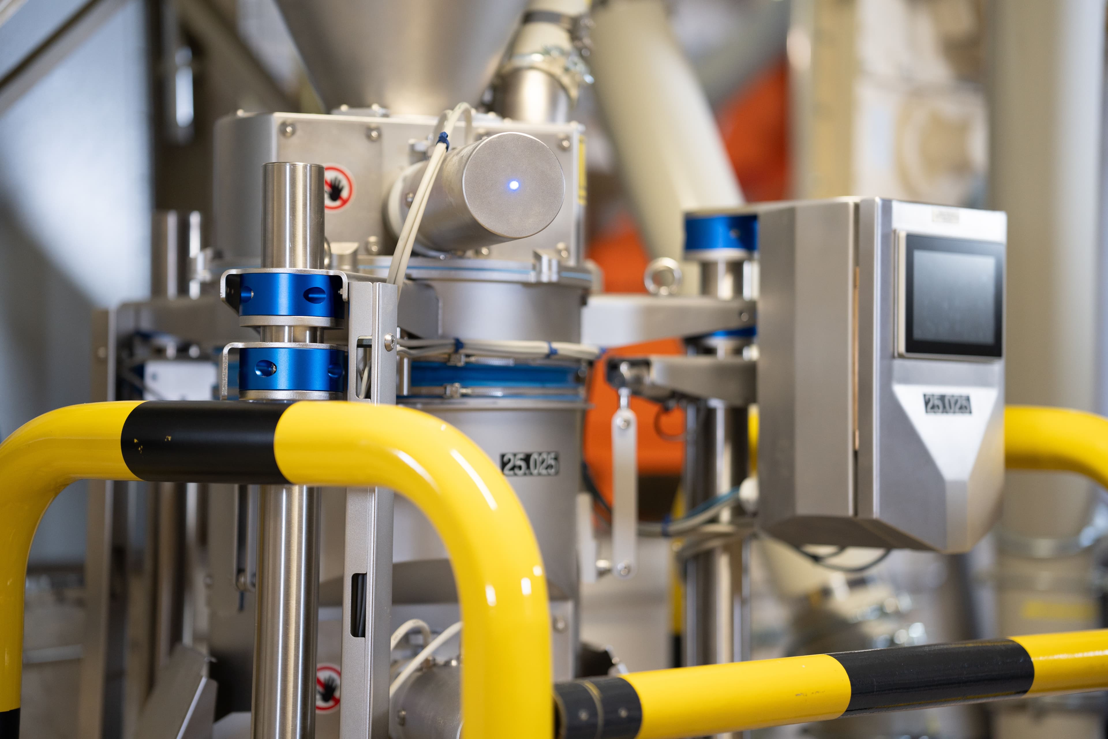
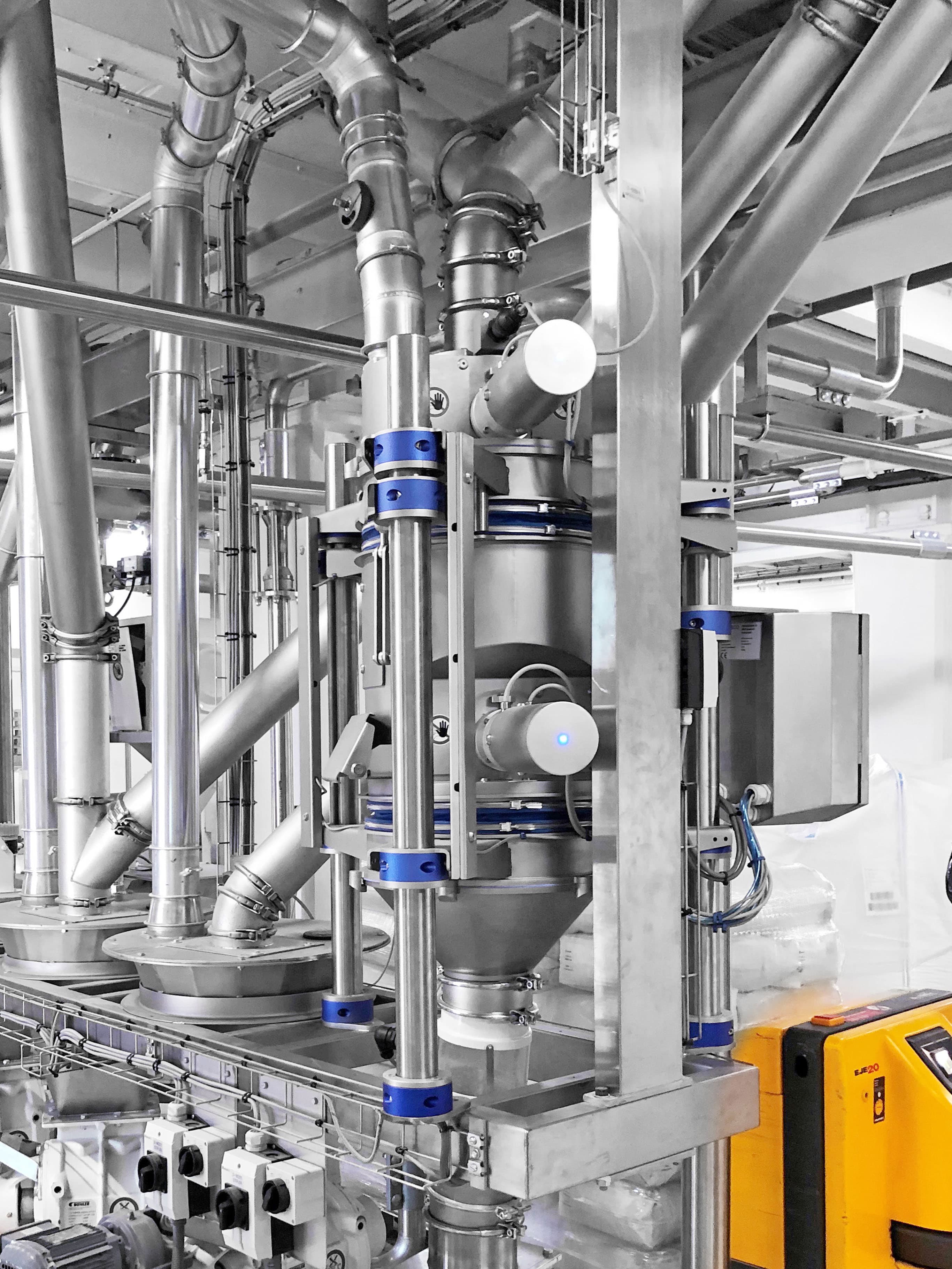
创新,以光速测量料位
由于自动化程度的提高,越来越多的智能传感器被用于制粉行业的创新应用。用于过程控制的重要的一类传感器是用于料仓和筒仓的高低料位检测、堆积防护、流量监测、范围测量和位置跟踪。在制粉工业中,最常安装的传感器方案是旋转式料位计、电容式探头和振动杆。旋转式料位传感器已被证明可用于颗粒状散装物料的料仓和筒仓的料位指示。一个桨叶由电机连续旋转。当与物料接触时,物料阻力大于桨叶的旋转的力量时,桨叶将停止旋转。位置开关检测到旋转的停止,产生信号给控制系统。自动防故障的旋转式料位传感器是粮食行业中众所周知的用于重要工艺的启动或停止。几十年来,电容式料位测量是一个成熟的方法。散装物料在传感器处引起电容的变化,并将其转化为开关信号。当物料特性变化,重复性标定探头是必需的;而且对于低容重物料,检测变得不可靠;电容式探头对灰尘沉积也很敏感。振动杆由压电陶瓷元件产生频率共振,物料覆盖了传感器,振幅被阻后产生信号。以上这些传感器可用在不同的安装位置,并且不受物料特性的影响。传感器的技术在不断发展。在粉尘含量高的环境中,料位测量的趋势是朝着非接触式传感器,特别是雷达测距方向发展。雷达是 "无线电探测和测距 "的缩写,意思是 "基于无线电的位置和距离测量"。这项技术是基于电磁波的。雷达装置发射出集中的电磁波,被物体反射成回波,然后由装置根据各种标准进行评估。电子装置产生一个电磁脉冲,当击中物料表面时,一些能量会被反射。这种所谓的回声信号被传感器识别出来,并通过传输时间的测量转换为一个位置的指示。转换时间是发射脉冲和接收到的回波信号之间的时间差。由于电磁波在空气载波介质中的传播速度可以等同于光速,这个简单的关系可以被用来计算到介质表面的距离。使用雷达技术可以在粉尘环境中准确测量料位。
采用雷达的传感器技术能够提供精确物体探测、测距和位置跟踪应用所需的高度精确的距离数据。在高更新频率下可以实现毫米级的分辨率。然而,在将雷达技术集成到智能产品设计中时,产品开发人员通常被迫在低功耗和高精度之间做出选择。对精度的要求会随着功率的限制而增加,因为这种技术在减少的功率预算情况下是有优势的。SWISCA为制粉应用开发了一种创新的距离测量解决方案,它结合了先进的相干雷达方法的精度和脉冲雷达系统的低功率要求。脉冲雷达在脉冲间歇关闭发送器以降低功耗。传统相干雷达系统发送连串的脉冲,并利用返回信号的精确相位测量。这需要高功耗和相关的较高功率耗散和较大的电子元件。采用皮秒级的时间分辨率,SWISCA传感器能够在100毫米至两米的范围内以毫米级的精度测量距离,同时将其用于低功率装置上。使用雷达物位测量设备总是存在着频率范围的问题。非接触式雷达传感器的工作频率高达130GHz,而引导式微波技术使用的频率相对较低,只有1GHz。一般来说,低频率明显不容易受到与工艺有关的干扰,如堆积和灰尘。在开发SWISCA的雷达传感器时,产品开发人员注重在粉尘环境中的耐用性和可靠性,采用了60Hz的频率范围。
在制粉工业中,利用智能传感器进行工艺优化的趋势不仅是新的应用,而且还支持面粉厂卓越运营。专门开发的用于制粉行业物位测量的传感器,电磁脉冲与返回信号的精确相位测量,为卓越运营开辟了新机会。这种新一代的雷达传感器可靠、耐用、对粉尘不敏感,不需要重新标定,实现了更高的精度,在满足制粉行业整体物位测量的高要求方面迈出了一大步。+D37